
US Natural Resources Conservation Service
Core4 Conservation Practices
Chapter 3i Vegetative Barriers
Vegetative barriers (also referred to as grass hedges) are narrow, parallel strips of stiff, erect, dense grass planted close to the contour. These barriers cross concentrated flow areas at convenient angles for farming. This practice differs from other conservation buffers because vegetative barriers are managed in such a way that any soil berms that develop are not smoothed out during maintenance operations.
This new conservation practice requires additional evaluation. State interim practice standards will be developed following guidance for an interim national practice standard to provide design and management details. This section reviews research and experience and provides the best guidance available at this time.
Vegetative barriers can be used for the following purposes:
• Control sheet and ril erosion, trap sediment, and facilitate benching of sloping cropland.
• Control ril and gully erosion and trap sediment in concentrated flow areas.
• Trap sediment at the bottom of fields and at the end of furrows.
• Improve the efficiency of other conservation practices.
The following benefits are provided:
• Retard and reduce surface runoff by promoting detention and infiltration.
• Divert runoff to a stable outlet.
• Entrap sediment-borne and soluble contaminants and facilitate their transformations.
• Provide wildlife habitat.
Coarse, stiff, hedge-forming grasses can withstand high water flows that would bend and overtop finer vegetation. They retard flow velocity and spread out surface runoff. Reduced velocity prevents scouring, causes deposition of eroded sediment, and lessens ephemeral gully development. Vegetative barriers can disperse flow where water enters other types of conservation buffers.
Tillage not only creates conditions conducive to water erosion, but directly moves soil downslope. Where conventional tillage is used, slope gradients between barriers become flatter and more uniform over time and contour lines gradually align with the barriers. Some tillage operations move soil directly into vegetative barriers. Berms formed in this way may divert runoff along the barriers in the same way that terraces redirect water. This diversion of runoff reduces erosion between barriers, but also results in increased flows of water and wetness where barriers cross low spots in a field. In these low areas, concentrated runoff is retarded and dispersed as it passes through the vegetative barriers.
Soil erosion occurs on all cropped landscapes. The rate of erosion depends on soil and rainfall characteristics, slope steepness and length, and land management practices. Landscape changes occur slowly on a cropped field, for any rate of soil erosion. Placing vegetative barriers on the landscape divides fields into cropped and vegetative strips. Even if the rate of soil erosion is reduced, the rate of translocation resulting from tillage remains constant within the cropped intervals and soil is removed from the upper part of each cropped area and deposited upslope of the next barrier. This process reduces soil depth downslope of barriers and increases it above them (fig. 3i-1), resulting in alterations in water holding capacity, rooting depth, and fertility. The desirability of these changes and their impact on the productivity of a particular soil should be considered in planning this practice.
When used in combination with contouring reduced tillage, and crop residue management, soil movement is small, large changes in slope do not occur, and therefore, the main impact of barriers is to disperse concentrated flow and prevent ephemeral gully development. When used in combination with filter strip or other buffer technology, the main impact is dispersed flow of run off entering the conservation buffer area. This ensures that sediment and associated contaminants are deposited above, rather than within, the buffer and will increase buffer effectiveness and longevity.
Location
This practice applies to all eroding areas, including but not limited to cropland, pastureland, rangeland, feedlots, mined land, gullies, and ditches. This practice is used in conjunction with other conservation practices in a conservation management system. Management practices, such as crop rotation and crop residue management, must be considered in designing the conservation management system on cropland. Associated structural practices, such as water and sediment control basins, subsurface drainage, and underground outlets, must be considered to adequately handle surface and subsurface water. This practice may improve the efficiency of other practices, such as strip cropping, filter strips, riparian forest buffer zones, grassed waterways, diversions, and terraces.
Design spacing and the lateral extent of vegetative barriers vary for the different purposes. They are described sequentially
Reducing sheet and rill erosion, trapping sediment, and facilitating benching of cropland
Figure 3i-1 is a definition sketch of a system of vegetative barriers placed on an initially uniform slope. The vertical interval (VI), or vertical fall between sequential hedge centers, is the parameter that limits hedge design spacing. The maximum VI for this purpose is the lesser of 6 feet (2 meters) or the spacing calculated by formulas for terraces (refer to Conservation Practice Standard 600, Terrace). On slopes less than 5 percent, the terrace standard often results in a maximum VI less than 6 feet. A VI less than the maximum value should also occur in areas that have shallow soils where deep benches are undesirable.
Vegetative barriers are arranged parallel to each other on or near the contour, but cross concentrated flow areas at angles convenient for farming. Over time, sediment and tillage fill in the low areas and contours adjust to conform closer to barriers. All tillage is done parallel to the vegetative barriers and contributes significantly to the leveling and benching between vegetative barriers.
Gradients along barriers should be 0.6 percent or less except where the vegetative barriers cross concentrated flow areas. Gradients entering a concentrated flow area may deviate from this criteria for a distance of 100 feet on either side of the concentrated flow area. This helps to get better row alignment.
In designing barrier systems for variable fields, one approach is to select a constant hedge spacing based on the steepest 30 percent of the field. This spacing is a convenient multiple of the working width of the field equipment. Lay out barriers starting at midslope. Keep upslope and downslope barriers parallel to facilitate field operations. Where variable slopes cause excessive deviations from the contour, extra barriers can be included on the gentler slopes to keep barriers on steeper and terrace P subfactors. After barriers slopes close to the contour (see case study). For more local irregularities, a barrier’s width may be altered along with the width of the cropped strip, with subsequent barriers being parallel to the new line.
Erosion control credit
Vegetative barrier practice benefits for soil erosion control may be calculated using the Revised Universal Soil Loss Equation (RUSLE). Erosion control credit comes from modification to the practice (P) and length and steepness of slope (LS) factors. This depends on the design, management, and maturity of the barriers. When initially established, the barriers serve as guides to contour cultivation and receive credit for contouring and stripcropping practice (P) subfactors that reflect alignment and vegetation characteristics. After barriers are well established and begin to create backwater that causes sediment to be deposited upslope of the actual vegetative barrier area, the effective width of the barrier should be used rather than the actual width of the grass in RUSLE computations.
Based on research results, the latest RUSLE recommendation is to use an effective strip width of the barrier as a percent of hillslope length. Twelve percent for hillslope steepness of less than 5 percent, 8 percent for slopes of 5 to 10 percent, and 4 percent for slopes of 10 to 15 percent. Backwater distances are negligible on slopes steeper than 15 percent.
For planning purposes, it is also worthwhile to use RUSLE to estimate the erosion that would occur if vegetative barriers diverted flow and acted as terraces. In this case, slope length is reduced to the barrier spacing, and the vegetative barrier systems receive conservation credit in both the LS factor and the contouring and terrace P subfactors. After barriers have been established for some years, the conservationist should inspect the field and determine if the barriers are functioning as terraces. If it is then it is appropriate to apply this approach.
Controlling rill and gully erosion and trapping sediment in concentrated flow areas.
Where sheet and rill erosion are controlled with other practices such as residue management, separate and discrete barrier sections may be installed across concentrated flow areas to control ephemeral gully development. When used to control only ephemeral erosion, barriers do not need to extend across the ridgetops but only long enough to prevent bypass flow around the ends. This bypass flow can be avoided if each strip is extended far enough to provide 1.25 feet of elevation above the base level section that will develop after a few years of sedimentation (fig. 3i-2). High on the slope where contributing areas are small, barrier lengths need not be this large.
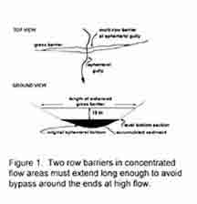
Figure 3i-2: Barriers must consist of at least two rows in concentrated flow areas and must extend long enough to avoid bypass around the ends at high flow. Level bottom section may develop from sediment accumulation above original bottom or may be created by minor earthmoving as part of barrier establishment.
A level base area adds stability to vegetative barriers in high flow areas (fig. 3i-2). Experience has shown that established barriers are stable if the length of the level base section (measured in feet) is numerically greater than the contributing area (measured in acres) of the watershed above the barrier. This level base section will form gradually over time, but where contributing areas are large, some earth-moving may be desirable prior to vegetative barrier establishment to create this level base section to disperse runoff. Barriers have special spacing and vegetation requirements in concentrated flow situations. Here, vegetative barriers should be at least 3 feet wide and consist of at least 2 rows of vegetation. The maximum VI for discontinuous barriers is reduced to 4 feet to minimize step heights. It may need to be only 2 feet on vertisols to avoid block failure of developed benches. Vegetation should be maintained at a height of at least 15 inches throughout the year. Stem density should exceed 50 stems per square foot and contain a sufficient density of large anchored stems (living or dead) so that the product of the large-stem density (M, number per square foot) times the large-stem diameter (D, inches, measured two inches above the ground) raised to the fourth power exceeds 0.1:
(M)x(D4)>0.1
As an example, for vegetation with 70 stems per square foot and stems 0.2 inches in diameter, the product is:
(70) (0.2)4 = (70) (0.0016) = 0.112
This is adequate for a concentrated flow barrier, but the greater the product the better. Where mixtures of vegetation exist, count only stems larger in diameter than the value (D) used in calculations.
As barriers are established and trap sediment, the slope of the landscape between them is reduced as a result of soil movement by tillage translocation and erosion/sedimentation processes.
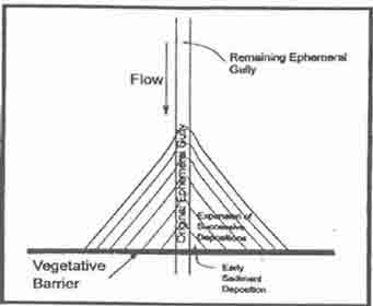
Concave areas where flows concentrate are most rapidly filled with sediment help to disperse flows (fig. 3i-3). Rills initially develop immediately below barriers in concentrated flow locations. Tillage smooths and spreads these areas laterally along the barrier. Subsequent storms move more sediment and deposit it upslope of the next barrier. The net effect is an accelerated benching of the landscape (fig. 3I -1) in concentrated flow areas.
Backwater created above each barrier protects the submerged areas from high velocity flows and further erosion (fig. 3i-4). Benching continues until the backwater from a downslope barrier submerges the base of the next barrier ups-lope and erosion below the upslope barriers ceases. Therefore, the most downslope barrier in a field should be located in the footslope area below which ephemeral gully development is not anticipated and where the velocity of dispersed runoff leaving the barriers does not exceed critical values for the soil conditions existing downs lope of the barrier.

Figure 3i-4. Top view showing spadng of barriers, backwaters, and re-concentration offlow downslope of barriers~ In situations where rows are bedded; flows wiil reconcentrate more rapidly than shown and backwaters should extend all the way to the next barrier to prevenifurther ephemeral gully development.
Trapping sediment at the edge of fields and/or the ends of furrows
Vegetative barriers may be used to trap sediment at the edge of fields and/or the ends of furrows whether the furrows are aligned up and down the slope, across the slope, or on the contour. Used as a field border, barriers can effectively reduce sediment delivery offsite, prevent the development of headcuts into the field, and ensure uniform overbank flow into streams and ditches. However, such barriers will not reduce in-field sheet and rill erosion rates, and those factors used in erosion prediction models should not be altered.
Utilization of subsurface drainage to remove water from sediment accumulated in the flattened areas above the barriers can avoid development of wet areas and combine to make these areas highly productive. A series of barriers spaced at a VI of 2 feet may serve as an inexpensive alternative to small drop pipe structures where bank slopes do not exceed 100 percent (1:1) and where shading by woody vegetation will not restrict vegetative barrier growth. Vegetative barriers used as field borders should be a minimum of 3 feet wide. There is no maximum crop strip width or slope length.
Increasing the efficiency of other conservation practices
Contour buffer strips: Field strips are similar to vegetative barriers except they are wider, have less stringent alignment criteria, and require sediment accumulations to be periodically removed and redistributed on the land. Vegetative barriers, established just upslope or in the upper 3 feet of the field strip where they cross concentrated flow areas, can disperse these flows so more of the runoff goes through, rather than over, the vegetation in the strips.
Filter strips: Filter strips are areas of vegetation located along streams, waterbodies, field borders, terraces, or diversions used to entrap sediment and improve water quality. Vegetative barriers incorporated into the upslope portion of filter strips improve uniformity of runoff flows entering the filter and increase filter strip longevity by promoting sediment deposition above the filter strip. Vegetative barriers can also be placed in the filter areas to promote ponding and infiltration.
Field borders: Field borders are areas of vegetation located along field edges or boundaries to provide wildlife habitat or access to the field. Vegetative barriers incorporated into the upslope portion of borders on the low side of the field will increase field border longevity by promoting sediment deposition above the field border. Vegetative barriers also provide additional wildlife cover in borders of predominantly sod-forming grasses.
Riparian forest buffers: Riparian forest buffers are similar to filter strips but include woody as well as herbaceous vegetation. Vegetative barriers could be used on the ups lope edge of the vegetation zones to disperse flow and provide more complete removal of nitrate from groundwater.
Grassed waterways: Waterways are designed to remove water from a field under controlled conditions. In some cases high flow velocities make establishment of grass difficult. Vegetative barriers can help stabilize waterways, much like the use of hay bales, when established at designed intervals across concentrated flow channels. Their uniform dispersal and slowing of runoff, together with their root systems, make established vegetative barriers more effective than hay bales.
Diversions and terraces: Diversions and terraces are designed to intercept water flowing down a slope and direct it across the slope to a stable outlet such as a grassed waterway or underground outlet. Vegetative barriers established above the diversion and terrace channels increase their longevity by promoting sediment deposition above the diversions and channels. Barriers established on top of terraces may provide additional stability, however, barrier vegetation should not be allowed to become established within the terrace channel area.
In all practice modification with vegetative barriers, ensure that the barrier vegetation does not direct sediment deposition into areas that would impair the function of the associated conservation practice.
Plant materials information
Species selection
Vegetative barriers should be planted to vegetation with sufficient stem strength and density to trap sediment and detain water. The stems of the vegetation should have the ability to remain upright during runoff flow events.
Other herbaceous and woody species may be used if they have proven ability to retard flow velocity and trap sediment. Cultivars of individual species with known superior stem strength will be used, for example, shelter switchgrass in the Northeast. Care should be taken not to select vegetation that is known to be invasive or that is a host for insect and disease pests in the region.
Vegetation should be established that has a density of at least 50 stems per square foot in all barriers. Barrier should be at least 3 feet wide. If barrier vegetation is so tall-growing that mowing is needed to minimize crop shading, barriers may be made wider to accommodate available mowing equipment. Mature barrier design width may also be wider than the amount of vegetation initially planted (fig. 3i-l).
The steepness of a stable backslope of the mature bench (Si, fig. 3i-1), which depends on local soil and vegetation characteristics, determines the required design barrier width. The final steepness of the cropped interval, (S2, fig. 3I -1) is reduced to a fraction of the initial slope.
Grass species native to the contiguous United States that possess desired characteristics include: Switchgrass (Panicum virgatum), Coastal panicgrass (Panicum amarum var. amarulum), Eastern gama.grass (Tripsacum dactyloides), Basin wildrye (Leymus cinerus), and Big sacaton (Sporobolus wrightii).
Desirable characteristics are found in these exotic grasses: Tall wheatgrass (Elytrigia elongata), Altai wildrye (Leymus cinerus), Mammoth wildrye (Leymus racemosus), Chinese silver grass (Miscanthus sinensis), and Vetivergrass (Vetiver zizanioides).
Method of establishment
Vegetative barriers may be established vegetatively or from seed. Vegetatively propagated barriers trap more sediment immediately and are not as subject to establishment failure from washouts or burial by sediment. Seeding requires less material and labor and, therefore, is less expensive.
Barriers established vegetatively should be planted at a spacing sufficiently dense-to ensure a functional hedge in one growing season. This spacing needs to be closer in areas that have limited rainfall. While planting a continuous sod strip would be best, experience in Texas indicates that planting a single row of slips (bareroot seedlings, cuttings, or divisions) at a 3-inch spacing created a functional hedge in 1 year, while planting at a 6-inch spacing takes 2 years. In more humid areas, 6 to 12 inch spacing have proved effective in 1 year. Even where gaps between transplanted clumps are still distinguishable, crop residue bridges these gaps and makes the hedge effective in slowing runoff and trapping sediment. In concentrated flow areas, a double row of continuous sod strips, or of rows planted with 6 to 8 inch spacing of 4 inch diameter clumps, with rows 12 to 18 inches apart, is recommended.
Barriers established from seed should be sown using the best available technology for establishing a stand with little risk of failure. In most cases this mandates the use of a drill to place the seed at the precise rate and depth recommended. Optimum seeding dates for the species are used. Irrigation should be used if it is part of the standard establishment procedures for the species. Seed should be sown in a strip at least 3 feet wide.
Establishment by plants or seed may be enhanced by installing straw bales, burlap silt fences, biologs, or fiber rolls immediately downs lope of the barrier location in concentrated flow areas. This reduces scour and promotes water conservation for the young plants.
Seedbed and planting bed
Poor site preparation is a major cause of stand failures. Therefore, site preparation should be planned and initiated well in advance of planting. No-till planting can be ideal provided weeds are thoroughly killed before planting. Seeds should be placed at optimum depth, and the seedbed packed after seeding.
Tilled seedbeds should be packed before seeding to create a firm surface for sowing and to ensure precise seeding depth control. Seedbeds should also be packed after planting to ensure good seed-to-soil contact. Plants to be established vegetatively may be planted into a loose bed, but the soil should be well packed after planting.
Planting dates
Vegetative plant materials are best transplanted when dormant or during periods of abundant rainfall in early spring. Seeded plant material should be sown at optimum seeding dates for the species, soil, geographic location, and irrigation potential.
Fertility
Lime, phosphorus, and potassium should be applied before planting. Their application should be according to soil test recommendations. Nitrogen, on the other hand, should not be applied at planting. Instead, it should be applied at recommended rates when the planted species have emerged and are competing well with weed species present.
Weed control
Weeds should be controlled with an integrated control strategy using cultural, mechanical, and chemical methods.
Planning considerations
Need for tile drainage
Where barriers cross low areas, sediment deposition results in reduced slopes and loose, unconsolidated sediment. Wheel ruts in this sediment, combined with residue trapped on the barriers, have been, observed to significantly impede surface<t drainage, thus interfering with field operations and lowering the area’s productivity. Because the barriers and associated tillage marks tend to redirect runoff, wet spots may be created where they never before existed. Farmers seeing this problem may be tempted to cut water furrows thorough the barriers to facilitate drainage. Subsurface tile installed perpendicular to grass barriers under the concentrated flow areas avoid these difficulties (see case study). Feeder tile lines buried under the hedge and connected to the perpendicular main tile further alleviate wet areas and decrease surface runoff and amounts of crop protection chemicals leaving the field.
Barriers as alternatives to a waterway
Waterways are designed to remove water from a field under controlled conditions. In some situations grass barriers can perform the same function even though their alignment is perpendicular to the direction of runoff flow. Barriers "step" water down the slope, relying on tillage and deposition of sediment to cause progressive leveling that disperses and slows runoff. Where flow conditions do not exceed barrier strength, a suitable merging of these technologies may be to leave small sodded areas below each hedge to control local erosion on hedge back-slopes while allowing crop production and tillage above each hedge that is accompanied by downhill soil movement and results in benching.
Application to construction sites
Vegetative barriers offer an attractive and effective alternative to silt fences and hay bales on construction sites. The high value of the area being protected and the need for immediate sediment control make vegetative establishment practical. Vegetative barriers are most effective if established in advance of construction. While vegetative barriers are easy to kill or remove after construction is completed, a more efficient approach would be to cut areas close to final grade prior to barrier establishment from stiff-grass sod strips and to allow the barriers and trapped sediment to remain as part of the permanent landscape.
Operation and maintenance
Any vegetative erosion control practice
requires maintenance. However, vegetative barriers generally
require less maintenance than waterways, buffer strips, or filter
strips because sediment deposits do not need to be redistributed
throughout the field. Also, repair of washouts is restricted to a
narrow width of vegetation. Where barriers are established from
seed, washouts are likely to occur in concentrated flow areas
during the establishment year. These areas can be repaired by
overfilling the damaged area and transplanting vegetation the
following year. Barriers in concentrated flow
situations should be inspected annually and any gaps, such as may
be created by animal burrows, should similarly be repaired early
in the spring. Maintenance must be done in a timely manner to
prevent further damage.
Another maintenance issue concerns training farm workers to distinguish barrier vegetation from weeds, such as johnsongrass. Young barrier grass should not be killed because it is mistaken for a weed. Remove weedy species that could be invasive to the cropped areas adjacent to the barriers. This can frequently be accomplished by using wick application of nonselective herbicides after a height differential has been developed following barrier mowing.
If wetness develops in sediment deposited upslope of barriers, farmers may be tempted to cut water furrows through the barriers to facilitate drainage. This damages the vegetative barrier system and should not be done. Tile drainage can avoid this problem
Tall-growing barrier grasses must be mowed to minimize shading of adjacent crop rows. Mowing produces barriers of denser, but finer stems. Mowing is therefore undesirable in concentrated flow areas if large stem diameters are desired. - Selecting barrier species that do not mowing, but that have dense thick stems, reduces maintenance and permits barriers narrower than mowing machine
widths.
Burning may stimulate growth of some hedge grasses, but is not a desirable practice in concentrated flow situations if tillage will soon follow and maximum sediment trapping effectiveness is needed.
Case Study
In 1992 Dillaha and Hayes presented an analysis of the application of filter strips to an irregular field (fig. 3i-5). These authors determined sediment trapping from a 10-year return interval design storm. According to those authors, the filter strip design they presented (fig. 3 i-6) trapped at least 97 percent of all sediment greater than 0.01 mm and 58 percent of clay sized sediment. The authors stressed that trapping of silt-sized sediment was greatly reduced if filter strips were not extended above points d and e as illustrated because depths of concentrated runoff exceeded 4 inches.
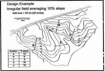
Figure 3i-5: Irregular 50-acre field averaging 10 percent slope bul ranging from 4 percent to 16 percent. Such fields result in complex designs requiring extra barriers on less steep portions of the field to maintain contour alignment. Contour interval is 6 feet (2m).
In 1995, Dabney and fellow researchers used this field in an example exercise to show how buffer strip, vegetative barrier, and hybrid systems might be designed. The systems developed are illustrated in figures 3i-6 to 3i-10. A comparison of the five systems is presented in table 3i- 1.
While the original vegetative filter strip design (fig. 3i-6) does a good job of reducing sediment yield, it does nothing to reduce sheet and rill erosion within the cropped portion of the field and it removes the greatest amount of land from production.
Table 3i-1: Comparison of land use and impact of alternative vegetative erosion and sediment control systems in case study example

Based on RUSLE calculations, the contour buffer strip design (Fig. 3i-7) reduced sheet and rill erosion in the field by about 25 percent. This is inadequate by itself as an erosion or sediment control system because of significant deviations of the strips from the contour at several points. This practice also removed a relatively large area of the field from crop production.
NOT AVAILABLE
Figure 3i-6: Dillaha and Hayes (1992) and Hayes and Dillaha (1992) showed that this filter strip design trapped 97 percent of sediment greater than 10 microns in diameter. However, this system does not control infield erosion.

Figure 31-7: Contour buffer strips sometimes deviate sign~f icantly from the true contour when applied to such irregular fields, reducing their erosion control effectiveness.
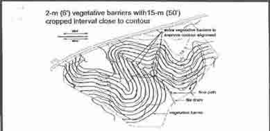
Figure 3i-8: This example illustrates the addition of extra parallel barriers on the southwest part of the field; that terminate near the drainage way in the center of the field These extra barriers are needed to maintain contour alignment in this irregular field The subsurface tiles help to avoid development of wet spots from flow re-directed by the barriers.
The contour vegetative barrier design (fig. 3i-8) removes less cropland from production than the filter strips or buffer strips and affords the greatest degree of in-field erosion control of any of the alternative vegetative systems studied. This system however, is also the most complex to design and establish and it provides less trapping of fine sediment than the filter strip design.
The vegetative barriers provide a guide for contour tillage, and tillage marks parallel to the barriers intercept flow and redirect it in the same way that terraces redirect water. This reduces effective slope length. RUSLE calculations of this system indicate that with this reduction in slope length and contouring benefits, sheet and riIl erosion may be reduced by 75 percent compared to no treatment of this cropped field. Runoff diverted to local depressions is carried downslope through the barriers under controlled conditions that prevent ephemeral gully development. Tile drainage is provided to avoid wet spots within the field where barriers have directed runoff water.
It should be noted that extra barriers are established on the southern, more gently sloping part of the field to maintain contour alignment on the steeper part to the north. In this arrangement, planting direction is reversed around the end of each extra barrier, and no point rows are created.
The discrete vegetative barrier system (fig. 3i-9) can control ephemeral gullies within fields but, like filter strips, does not control sheet and rill erosion throughout the field. This system removes the least amount of land from production of all the systems compared, but could create problems with row alignment unless planting is done with a grain drill.
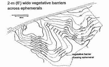
Figure 3i-9. The use of discrete barrier sections can control ephemeral gully development; however, the irregular spacing could create row alignment problems if cultivation or directed spraying is needed.
Figure 3i-10. This hybrid system uses a filter strip to reduce sediment yield, and discrete vegetative barriers to control ephemeral gullies. This system is most effective and practical when used in combination with crop residue management to control sheet and rill erosion.
The hybrid system (fig. 3i-10) combines a filter strip, one continuous vegetative barriers to serve as a guide for row directions, and discrete vegetative barriers to control ephemeral gullies. This system has several advantages.
• Sediment trapping of all but dispersed clay will be nearly equal to that of the original filter strip design while taking less than half as much land out of production.
• Ephemeral gully erosion is controlled within the field.
• The upslope of the filter strip includes a vegetative barrier that protects the filter strip from inundation with concentrated flow during large storms.
• Most of the sand and aggregated sediment in runoff will deposit within the cropped part of the field. This helps maintain field productivity and extends the life of the filter strip. By combining the hybrid system with crop residue management to control sheet and rill erosion in the field, an optimized runoff and erosion control system is created.
Background research
Vegetative barriers have potential for reducing sheet,rill, and ephemeral gully erosion and trapping sediment on cropland. Conventional grass buffer strips and filter strips can often fail where flow concentrates because the force of the flow flattens the grass which is then submerged and often buried under deposited sediment. Stiff erect grasses extend the range of conditions where grass strips can control runoff and sediment yield by withstanding higher flow rates and deeper sediment deposits.
Stage-discharge relationship
In 1996, Dabney reported an equation to predict backwater depth as a function of flow and grass barrier characteristics. Strips from 0.15 to 0.50 m wide were studied in specially designed flumes. Backwater elevations were determined for clearwater flows, q, ranging from 0.01 to 1.0 cubic foot per second per foot of barrier, typical of those occurring in upland runoff channels. Vetiver grass and switch-grass had the greatest ability to stand against high flows; 1-foot-wide barriers of each stood against backwater depths as great as 15 inches. The increased water depth at the upstream edge of a grass was bimodal function of flow, being nearly a linear function of flow up to 0.13 cubic foot per second per foot of barrier and proportional to the square root of flow rate at higher flows. Backwater depth was also a fractional (0.17) power function of stem density, stem diameter, and hedge width. In flows with sediment, backwater depths were found to be increased by the introduction of soil into the flow as the barriers became loaded with plant residue and duff from the soil (Meyer et al., 1995; Dabney et al., 1995b).
Sediment trapping
Deposition of sediment upslope of the grass is the primary mechanism for trapping sediment by vegetative barriers (Dabney et al., 1995b). Barriers do not filter sediment because they have relatively large flow spaces. Only large material, such as fibrous plant residue are trapped by filtration. Sediment trapping efficiency depends on the ponded depth (hedge density and flow rate), backwater length (slope), flow rate, and sediment size and density.
On hillslopes without concentrated flow, barriers trap about two-thirds of the sediment generated on small plots (McGregor and Dabney, 1993; Dabney et al., 1993; McGregor et al., 1998). Where flows concentrate, slope has a major impact on the length of the ponded area, and hence on sediment trapping. Meyer (1995) showed that for 0.05 slope and flows up to 0.5 cubic foot per second per foot of barrier, trapping efficiency of effective barriers was above 90 percent for sediment particles larger than 125 p.m diameter and about 20 percent for sediment smaller than 32 p.m. Between these sediment sizes, trapping effectiveness decreased with increasing flow rates. The 20 percent trapping of sediment finer than 16 p.m reported by Dabney (1995b) was greater than predicted by settling theory, suggesting some unidentifled mechanism was operative in removing fine sediment. Trapping of fine sediment is increased greatly if flows are dispersed, and so slowed, or if benching reduces slope and so increases settling distance (Dabney et al., 1995b; Dabney et al., 1996).
Hedge failure prediction
A barrier’s strength, its ability to remain erect, is related to its stem density and its individual stem strength. The product MEl (where M is stem density, E is stem modulus of elasticity, and I is stem moment of inertia that is proportional to the fourth power of stem diameter) has been suggested as an indicator of hedge strength and is the basis for the barrier strength criteria provided earlier. Dunn and Dabney (1996) found that modulus of elasticity of stems of several grasses increased with stem age. Vetiver grass barriers develop strength from a high density of large diameter stems, whereas switchgrass barriers are strong because of the high modulus of elasticity, similar to that of oak, of their intact mature stems.
Landscape evolution
The soil conservation effectiveness of a well-maintained system of vegetative barriers increases with time. As soil is removed downslope of barriers and sediment is trapped upslope, the steepness of the cropped interval and ephemeral slope is reduced. This slows runoff, reduces erosion, and increases potential water infiltration and crop productivity. Where soil is tilled and sediment loads are high, deposition upstream of barriers can significantly flatten concentrated flow areas over time, further spreading and dispersing runoff (fig. 3i-3). The ability to survive and thrive as sediment is deposited in and around them enables stiff grass barriers to maintain their trapping capacity after each deposition event. In fact, as sediment deposits as a delta, depth of rooting increases, as does the ability of the soil to store the supplemental water carried to swale areas with runoff. These conditions commonly facilitate more plant growth than occurred previously. This increasing vegetative growth adds to the stability of the barrier, further slowing flow through it and allowing more sediment to settle.
Enhanced soil productivity immediately upslope of the barrier may be associated with a decline in productivity immediately downslope of the barrier where topsoil has been removed by tillage and erosion. The consequence is that substantial gradients of soil fertility and other soil properties may develop across the benches (Turkelboom et al.1997). The suitability of a site for benching depends on subsoil characteristics and the ability of a fanning system to overcome constraints imposed by subsoil exposure. Application of lime, manure, crop residue, fertilizer, and deep tillage may ameliorate any problem that develops in progressive areas.
Tillage translocation
Recent research has indicated that soil movement by tillage, termed tillage translocation, may be more significant than has been commonly recognized (Lindstrom et al., 1992; Govers et al.,1994; Lobb et al., 1995). Water erosion is more visible than tillage translocation and -is often the dominant means of transport in areas where concentrated ephemeral flow occurs. However, the ability of tillage to make the gullies that form in these areas, ephemeral proves that tillage can move just as much soil. Recent European studies (Quine et al., 1994, Govers et al., 1996) have reported that tillage accounts for 50 to 70 percent of total soil movement in conventional tillage agriculture on soils with gradients of 0.15 to 0.20.
Tillage erosion at a point depends on the balance of soil translocated into the control volume compared to the amount translocated out of that volume. If slopes are uniform, there are equal additions and removals in the control volume so change at that point is zero and tillage translocation goes unseen. On continuous slopes, tillage translocation causes visible changes only where slope gradients change; it causes degradation on convex slopes and aggradation on concave slopes. Tillage translocation is also evident at field boundaries, which are lines of zero flux. This is why vegetative barrier systems, by creating a large number of discontinuities and field boundaries and shortening slope. length, amplify the impact of tillage translocation on landscapes (Dabney et al., 1998). Tillage, by moving soil and by predisposing the soil to water erosion, is the predominant factor causing benching between vegetative barriers. Little landscape benching will occur in no-till situations.
Modeling difficulties and conservation credit Current generation erosion models, including RUSLE and WEPP, do not reflect any changes in slope over time and so cannot predict long-term conservation benefits. They also do not account for tillage translocation.
Observation of field plantings indicate that barriers and associated parallel tillage marks cause considerable redirection of runoff flows to localized low areas. As noted, this redirection can cause development of wet areas that require drainage. However, redirection also reduces runoff immediately downslope and so reduces effective slope length for nonflow areas. Current generation erosion models cannot account for partial redirection of runoff. Consequently, determination of effective slope length becomes a matter of judgement. In planning, if one assigns the credit expected with the current slope after vegetation is well established, the design should be very conservative because performance should improve with time if the barrier is properly maintained. If in the future the conservationist observes that slopes have been reduced or that flow is being redirected by the barriers behaving as terraces, it would then be appropriate to take additional credit by altering the modeled slope length and steepness.
Information needed to fill in job sheet
The job sheet provides information for the design of a vegetative barrier. The following is guidance in how to complete the specification sheet for the landowner’s use.
Landowner
Enter the name of the landowner planning the vegetative barrier.
Field number
Enter the field number or numbers from the conservation plan, job sketch, or plan map. A field name is sometimes more commonly used. Correspond the field identification with the job sketch on the backside of the job specification sheet.
Purpose
Check the appropriate purpose or purposes that the vegetative barrier will serve.
Location and layout
Cropped strip width - Using the field slope and vertical interval for the set of vegetative barrier determine the spacing between each barrier. Cropped strip width is the distance between each barrier on the slope. The area between barriers is considered the cropped area. Refer to figure 3i- 1. Make necessary adjustments for soil conditions, equipment size, and irregular slopes and drainageways.
Barrier width - The thickness of the vegetative barrier. This is measured by the width that the vegetation will occupy in the cropped area.
Rows per barrier - Determine the number of rows per each barrier. Infield barriers generally have only one or two rows. Barriers crossing drainageways have two or more rows. Barriers may be solid, seeded in row widths from 12 to 36 inches wide. Wider barrier widths are sometimes used to correct point rows on irregular slopes.
Barrier length (feet) - Determine the length of each barrier across the landscape. Length is measured perpendicular to the flow direction of water across the field. Some vegetative barriers will only cross drainageways while others may traverse the entire slope.
Barrier acres - Calculate the total acreage established in vegetative barriers. This is the width of each individual barrier multiplied by the length of that barrier. Barrier acres determine seeding requirement.
Field slope - Measure the percent slope between each barrier. This percentage is used to calculate the vertical interval.
Plant material information
Provide the vegetation species and/or cultivar planned to be planted in each vegetative barrier Acceptable species are listed in the Field Office Technical Guide. The seeding rate or transplanting distance, planting date, and any recommendations for soil amendments and fertilizer are also given. Soil is applied according to a soil test or following the guidance in conservation practice standard for critical area treatment. Follow recommended timings of soil and fertilizer amendments.
Site preparation
Site preparations follow normal seeding and transplanting guidelines from conservation practice standard critical area treatment (342). Additional guidance can be given in Additional Specifications and Notes on the back page.
Planting method(s)
Specify the seeding depth or transplant spacing. Generally grass seeds are planted shallow (top 0.25 inch) in a firm seedbed. Give the amount and placement of mulch material, if used. Planting methods guidance is given in conservation practice standard critical area treatment (342). Use this same guidance to recommend planting grain cover or nurse crop.
Operation and maintenance
In this section provide guidance for any routine operations that are necessary to maintain the function of the vegetative barrier. Provide weed control methods based on vegetation tolerance to herbicides, tillage, mowing and/or burning. Program tillage and mowing to maintain row width and row height. Recommend fertilizer according to both crop and barrier needs. Give reminders to repair gaps in the barriers and where to obtain seedlings for repair. Caution against using herbicides in the cropped areas that will damage the vegetation in the barrier. Use Additional Specifications and Notes on the back page for providing the information to the landowner.
Job Sketch
Draw a sketch on the back page that shows field locations of
each vegetative barrier. Number each barrier. Show all
drainageways where the barrier will be realigned and planted to
additional rows. Show field boundaries, barrier widths, and slope
direction. Also show any other conservation buffer practices that
may be planned for the field.
Additional Reading
Dabney, S.M., Z. Liu, M. Lane, and J. Douglas. 1998. Landscape benching from tillage erosion between grass hedges. Soil and Tillage Res. (In review).
Dabney, S.M., K.C. McGregor, L.D. Meyer, E.H. Grissinger, and G.R. Foster. 1993. Vegetative barriers for runoff and sediment control. In Mitchell, J.K. (ed.) Integrated Resources Management and Landscape Modification for Environmental Protection, American Society of Agricultural Engineers, St. Joseph, MI., pp. 60-70.
Dabney, S.M., L.D. Meyer, G.H. Dunn, G.R. Foster, and C.V. Alonso. 1996. Stiff-grass hedges, a vegetative alternative for sediment control. Proceedings of the Sixth Federal Interagency Sedimentation Conference, Vol. 2(X):62-69.
Dabney, S.M., J.C. Hayes, and J.L. Lemunyon. 1995a. Controlling cropland and sediment loss with vegetative filter strips and grass hedges. 50th Annual Meeting of the Soil and Water Conservation Society, Des Moines, IA.
Dabney, S.M., L.D. Meyer, W.C. Harmon, C.V. Alonso, and G.R. Foster. 1995b. Depositional patterns of sediment trapped by grass hedges. Transactions of ASAB 38:1719-1729.
Dabney, S.M., L.D. Meyer, and K.C. McGregor. 1997. Sediment control and landscape modification with grass hedges. In S.Y. Wang, E.J. Langendoen, and F.D. Shields, J.R eds. Proceedings of the Conference on Management of Landscapes Disturbed by Channel Incision, Univ. of MS., Oxford, MS, pp. 1093-1099.
Dewald, C.L., S. Bruckerhoff, S. Dabney, J. Douglas, J. Heniy, J. Ritchie, D. Shepherd, and D. Wolf. 1996. Guidelines for the establishment of warm-season grass helges for Erosion Control. J. Soil and Cons. 51:16-20.
Dillaha, T.A., and J.C. Hayes. 1992. Vegetative filter strips:II. Applicati6n of design procedures. ASAE Paper No. 922103. American Society of Agricultural Engineers, St. Joseph, Ml.
Dunn G.H. and S. M. Dabney, 1996. Modulus of elasticity and moment of inertia of grass hedge stems. Transactions of the ASAE 39(3):947-952.
Govers, G., T.A. Quine, P.J.J. Desmet, and D.E. Walling. 1996. The relative contribution of soil tillage and overland flow erosion to soil redistribution on agricultural land. Earth Surface Proces. and Landforms 21:929-946.
Govers, G., K. Vandaele, P.J.J. Desmet, J. Poesen, and K. Bunte. 1994. The role of tillage in soil on hillslopes. European J. of Soil Sci. 45(4):469-478.
Kemper, D., S. Dabney, L. Kramer, D. Dominick, and T. Keep. 1992. Hedging against erosion. J. Soil and Water Cons. 47(4):284-288.
Lindstrom, M.J., W.W. Nelson, and T.E. Schumacher. 1992. Quantifying tillage erosion rates due to mold board plowing. Soil and Tillage Res. 24(3):243-255.
Lobb, D. A., R.G. Kachanoski, and M.H. Miller. 1995. Tillage translocation and tillage erosion on shoulder slope landscape positions measured using ‘37cs as a tracer. Can. J. Soil Sci. 75:211-218.
McGregor, K.C., and S.M. Dabney. 1993. Grass hedges reduce soil loss on no-till and conventional-till cotton plots. Proc. So. Conserv. Till Conf. for Sustainable Agr. pp. 16-20.
McGregor, K.C., S.M. Dabney, and J.R. Johnson. 1998. Runoff and soil loss from cotton plots with and without stiff-grass hedges. Trans. ASAE (submitted).
Meyer, L.D., S.M. Dabney, and W.C. Hannon. 1995. Sediment-trapping effectiveness of stiff-grass hedges. Transactions of ASAE 38(3):809-815.
Quine, T.A., P.J.J. Desmet, G. Govers, K. Vandaele, and D.E. Walling. 1994. A comparison of the roles of tillage and water erosion in landform development and sediment export on agricultural land near Leuven, Belgium. In L. Olive, R.J. Loughran, and J. Kesby (eds.) Variability in stream erosion and sediment transport., Proc. Canberra Symposium, IAHS Pub. 224., pp. 77-86.
Toy, T.J. and G.R. Foster (eds). 1998. Guidelines for the use of the Revised Universal Soil Loss Equation on mined lands, construction sites, and reclaimed lands. Office of Surface Mining, Reclamation, and Enforcement. (in press)
Turkelboom, F., Poesen, J., Ohler, I., Van Keer, K., Ongprasert, S., and Vlassak, K. 1997. Assessment of tillage erosion rates on steep slopes in northern Thailand. Catena 29:29-44.
United States Department of Agriculture-Soil Conservation Service. 1954. A manual on conservation of soil and water. Agriculture Handbook No.61. Washington, DC. pp. 87-89.